|
Final Assembly Instructions for the TLG-1800-GT Wind
Generator
(at the bottom is a link to a text only page for printing)
Click any image on this page to view full size
When your unit arrives please open the top of
the box and remove the blades,
hub, vane section, and hardware.
Please get assistance when you are ready to lift the generator yaw assembly
out of the box. The unit weighs about 65 pounds without the rotor blade
assembly.
Assembly of the Rotor Rotor
Before you mount the blades
please place a thin layer of silicone around the mounting holes up to the
end of the arm, and one
pencil size lines down the center and one pencil size at outside edge of the hub arm
opposite of the bolt holes.
Failure to do this will create a harmonic ring in the blades when
generating. (you will hate yourself if you do not apply silicone)
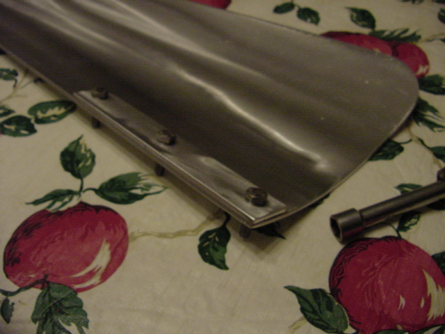
Insert all blade front washers onto the blades as shown in (figure D)
Insert the bolts into the hub arm as shown in (figure D1) add the flat
washer then the locknut to the bolt.
NOTE: the flat side of the blade runs flush (smooth) with the side of
the hub arm.
Tighten the center bolt snug to where you could bump the blade with your
hand to move it if
needed.
Use (something straight) a mini level etc to help you align the blade edge
to the hub arm. (if needed)
Tighten up the remaining two bolts along with the center one that you just
had snug.
Recheck the blade to make sure it is still running straight down the hub arm
wipe up excess silicone from the edge of the blade. Make sure the
curve part of the blade is contacting silicone between it and the hub.
Add more to fill the gap if needed.
Repeat the process for the remaining two blades. Allow silicone to set
up before mounting or using the assembled rotor assembly.

Figure D |

Figure D1 |
The rotor is now assembled and ready to mount to
the TLG-1800-GT shaft as soon as the silicone has set up.
At this time you have a decision to make!
Are you going to mount the rotor to the generator and raise it as
a complete unit?
Or are you going to mount the rotor to the generator after the yaw
assembly has been mount on the pole?
Proceed to the correct procedure below per your decision.
Mounting the Rotor to the TLG-1800-GT Head
Hook all three of the lead wires of the generator
together to apply a shunt brake.
Remove the nut and lock washer from the shaft along with the shaft adaptor.
Put a thin coat of silicone inside the shaft adaptor and put it back on the
shaft. Now place a thin layer of silicone around the raised lip on the
adaptor. Place the hub on the shaft followed by the lock washer and
nut.
Tighten the nut with a wrench or socket. Make
it tight but don't be stupid! ;)
That completes the rotor to the generator head, either on
the pole or on the ground
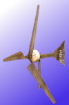
The Rotor should look like this mounted on the
Assembly.
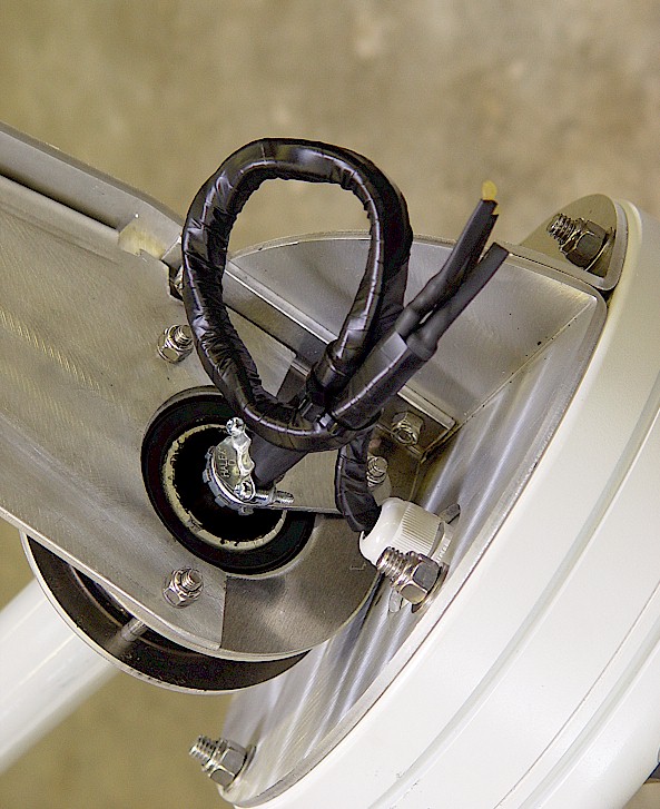
Hooking up the wires of the generator head to the
10/3 drop
wire (extension cord)
See figure E below for reference
Run the extension cord through the strain relief on the yaw
assembly. (figure E)
Tighten the two screws on the strain relief.
Cut and strip the wires of the extension cord.
It is ok to cut down the length of the wire coming out of the TLG-1800-GT head
to make a neater install.
Place a piece of heat shrink tubing (not supplied as it is optional) over
each wire of the generator head.
Twist the wires from the extension cord and the TLG-1800-GT together.
Solder or use wire nuts on each wire then cover with heat shrink tube, OR use a good amount of electrical tape.
If you want, you can add an extra hose clamp to the extension cord just
right above the stock strain relief for added support for the drop wire.
Wiring Note: When
you get to the control module it does
not matter which of the 3 wires connect where to it, (it's AC).

Figure E
For reference only, TLG-1800-GT not shown here.
Mounting the Yaw Assembly to the
1.5" Schedule 80 Receiver Pipe
NOTE: If you
purchased a split collar (LC-split1.5) with the unit please install the collar at exactly
2 inches down from the top of the Schedule 80 pipe before you place the TLG-1800-GT on the
pole. The split collar really simplifies the mounting on the pole
process. With a split collar you can just sit the generator assemble
on the pole and tighten the two set screws without having to raise the unit
from resting on top the pipe.
There are two set screws in the lower bearing housing.
(figure F) You will need a 3/16" Allen wrench for this part.
Sit the TLG-1800-GT over the 1 1/2" pipe unit it touches the strain relief
plate.
Raise the unit 3/16 of an inch up and tighten the first of the two set
screws with your 3/16" Allen wrench.
Tighten the second set screw... NOW back it off and retighten it again.
You will notice is goes in a bit further.
Repeat the back off, and retighten process to the other set screw to make
sure both set screws on the bearing are seated in the pipe.

Figure F
Mounting the Inverter, Dump
Element, and Controller and hooking the extension cord
from the TLG-1800-GT to the
controller module
The Inverter comes with (three)
3 foot long wires that have the appropriate connections installed. One
RED wire, one BLACK wire, and one wire with a 15 amp 250 volt plug on the
end. When mounting the Controller box and Inverter they need to with
within 3 feet of each other so the red and black wire can connect from the
controller and the Inverter. Likewise the power lead must be able to
reach from the inverter to the supplied 240 volt receptacle to plug in.
Once you have all three pieces mounted in close proximity of each other you
are ready to make the connection to the control module.
Remove the top cover from the control module. Inside the cover you will find
the wiring diagram in the inside of the lid for the connections for the
turbine, dump element, and inverter which go as follows. IN1 IN2 IN3
(wind turbine connections) in any order. B1 B2 and E1 (white wires and
green wire from dump element). DC+ and DC- (red and black wire from
inverter) red + / black -.
Run the 10/3 cord from the turbine through the bottom left hole, the dump
element through the bottom middle hole, and the red and black wire through
the bottom right hole. Doing this will place your connection closest
to the entry point of the box
The 3 foot cord from the inverter which has the 15 amp 250 volt plug will
plug into the supplied receptacle to your house hold 220 volt service
(please connect this to a 15 amp 220 breaker in your service panel (breaker
box).
That's it you are ready to go
online and produce some of your own energy.
Revisions may come based on end user
feedback
Back to the Instructions
page
Back to the TLG-1800-GT page
Home
TEXT ONLY PRINTING NOT READY AT THIS TIME
|